

Menu
Drill pipe forms the main tubular section of the drill string, using a steel pipe body with upset ends and weld-on tool joints to transmit axial load and rotary torque while carrying drilling fluid to the bit. During rotation, it also experiences cyclic bending, internal pressure, and repeated contact with the wellbore or casing, so pipe-body strength, upset transitions, weld quality, and tool-joint capacity all affect service performance.
The range below covers standard drill pipe in different sizes, grades, upset types, connections, and length configurations for oilfield drilling applications.
| Supply Item | Drill Pipe Range |
|---|---|
| Applicable Standard | API 5DP |
| Size Range | 2 3/8 in. to 6 5/8 in. |
| Main Grades | E75, X95, G105, S135 |
| Upset Types | IU, EU, IEU |
| Connections | NC26, NC31, NC38, NC40, NC46, NC50, 5 1/2 FH, 6 5/8 FH |
| Length Range | R1, R2, R3 |
Drill pipe is selected as a complete pipe-body and tool-joint configuration. OD, nominal weight, and grade define the main pipe section, while upset type, tool-joint OD/ID, and connection affect torque capacity, internal flow area, and external clearance.
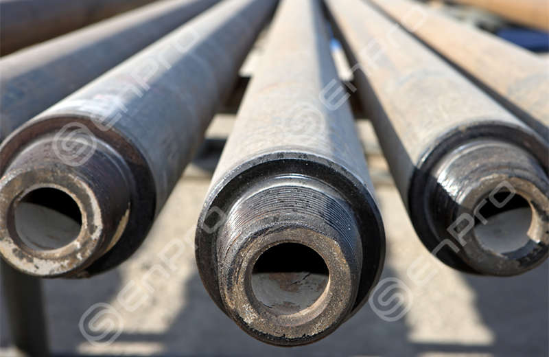
API 5DP defines the technical requirements for steel drill pipe, covering the pipe body, upset ends, weld-on tool joints, material grades, mechanical properties, dimensions, inspection, and product specification levels. It provides the main basis for specifying conventional drill pipe such as E75, X95, G105, and S135, while rotary shouldered connection threading and gauging are covered by API Spec 7-2.
| Item | API 5DP Scope |
|---|---|
| Product Standard | API Spec 5DP, 2nd Edition |
| Construction | Upset pipe body with weld-on tool joints |
| Product Levels | PSL-1, PSL-2, PSL-3 |
| Main Grades | E75, X95, G105, S135 |
| Sour-Service Grades | SS75, SS95, SS105 |
| Connection Reference | API Spec 7-2 |
| International Reference | ISO 11961:2018 |
The PSL-1, PSL-2, and PSL-3 structure allows additional technical requirements to be specified according to the drilling program. The selected PSL affects material qualification, mechanical testing, impact testing, inspection, and documentation, with tighter control applied as the specification level increases.
The familiar E75, X95, G105 and S135 designations represent progressively higher pipe-body yield-strength levels. API drill-stem property tables use 75 ksi for E75, while the X95, G105 and S135 designations correspond to minimum yield-strength levels of 95, 105 and 135 ksi respectively.
| Grade | Minimum Yield Strength | Approx. MPa | Typical Selection Consideration |
|---|---|---|---|
| E75 | 75 ksi | 517 MPa | Lower-strength drill string configurations where required tension and torque remain within the selected pipe/tool-joint capacity |
| X95 | 95 ksi | 655 MPa | Increased axial and torsional demand while retaining a moderate strength level |
| G105 | 105 ksi | 724 MPa | Higher drill-string loads, deeper sections and demanding directional drilling programs |
| S135 | 135 ksi | 931 MPa | High tensile and torsional demand in deep, extended-reach or heavily loaded drill strings |
Grade selection follows the actual load carried by the drill string. In deep or deviated wells, string weight, torque, dogleg bending, internal pressure, and fatigue act together, so the pipe body, tool joint, and connection need to be evaluated as one assembly.
For example, API RP 7G data for 3 1/2 in., 13.30 lb/ft drill pipe gives pipe-body torsional yield values of about 23,498 ft-lb for X95, 25,972 ft-lb for G105, and 33,392 ft-lb for S135. As the pipe-body strength increases, the selected tool joint and connection need corresponding torsional capacity to carry that load through the string.
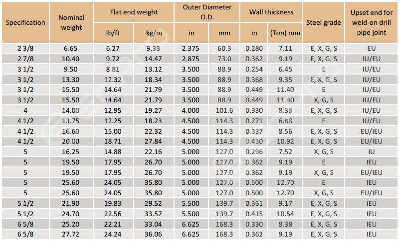
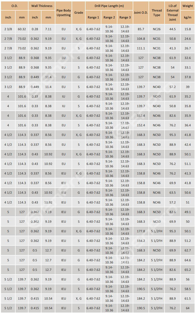
Drill pipe specifications combine pipe size, nominal weight, grade, upset type, tool-joint dimensions, connection, and length range. These parameters define the pipe’s strength, flow area, and drill-string compatibility.
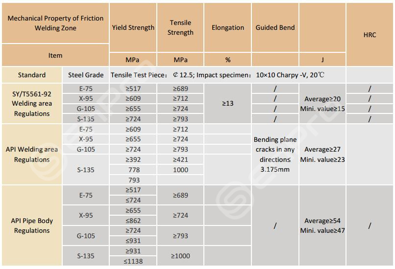
The mechanical performance of drill pipe depends on both the pipe body and friction-welded zone. The table compares yield strength, tensile strength, elongation, bend performance, and Charpy impact requirements for E75, X95, G105, and S135, showing how strength and weld-zone acceptance change with grade.
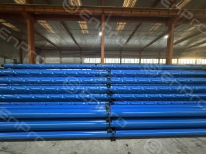
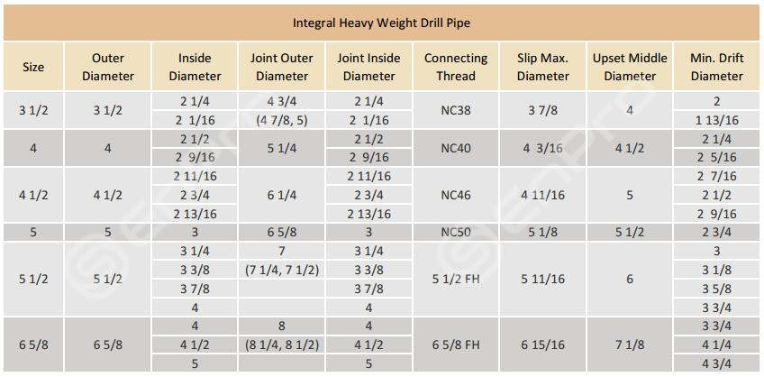
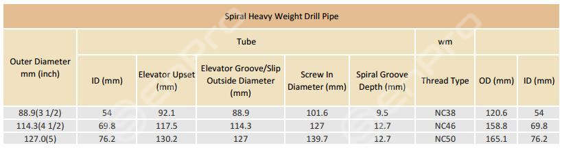
Heavy weight drill pipe (HWDP) is available in integral, spiral-weight, and welded configurations to match different drill-string load and wear conditions. The main differences lie in the body construction, center-section geometry, tool-joint arrangement, connection type, and internal/external dimensions.
 Spiral Weight Heavy Weight Drill Pipe
 Welded Heavy Drill Pipe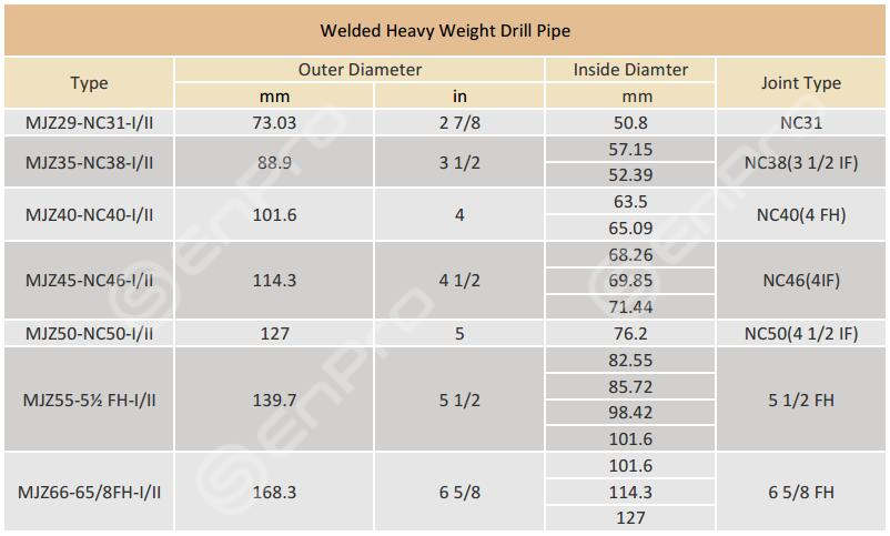
Heavy weight drill pipe uses 4145H alloy steel with a Cr-Mo composition suited to the higher bending and compressive loads near the BHA. The material shown here has minimum 758 MPa yield strength, 965 MPa tensile strength, 13% elongation, with 285–341 HB hardness and Charpy impact energy of at least 54 J.


API 5DP drill pipe is manufactured as two controlled parts: the seamless pipe body and the tool joints. The pipe body is first rolled to the required OD and wall thickness, then both ends are heated and forged into IU, EU or IEU upsets. The upset increases the section available around the pipe end and creates the transition needed for attaching the heavier tool joint. After upsetting, the pipe body receives grade-specific heat treatment and straightening to develop the required E75, X95, G105 or S135 mechanical properties. ISO 11961 defines finished drill pipe specifically as a product with upset pipe-body ends and weld-on tool joints.
Pin and box tool joints are produced separately, heat treated, and machined to the specified tool-joint OD, ID, shoulder and rotary connection geometry. They are then friction welded to the upset pipe ends. For other metal fabrication applications, a laser welding machine can provide precise and consistent welds.After welding, the internal and external flash is removed and the weld area receives the required thermal processing before final dimensional and mechanical inspection. API 5DP treats this weld as a separate acceptance zone: for conventional E, X, G and S grades, weld-zone surface hardness must not exceed 37 HRC.
Final production includes thread machining and gauging, wall-thickness verification, NDE, dimensional inspection and marking. API 5DP requires each pipe body to have wall thickness verified along its length by a helical or longitudinal inspection path, with separate control for end areas that automated equipment cannot cover.
Pipe body forming → upsetting → heat treatment → straightening → tool-joint machining → friction welding → weld-zone treatment → thread finishing → NDE and dimensional inspection → marking
Drill pipe and heavy weight drill pipe work in different sections of the drill string. Standard drill pipe forms the main rotating tubular string, while HWDP is normally positioned closer to the BHA, where higher compression, bending and contact loads require a heavier and stiffer section.
For H₂S-containing drilling, conventional API 5DP drill pipe can also be specified using the applicable SS75, SS95 or SS105 sour-service requirements. HWDP sour-service suitability should be confirmed separately against its material specification, heat treatment and project environmental requirements.
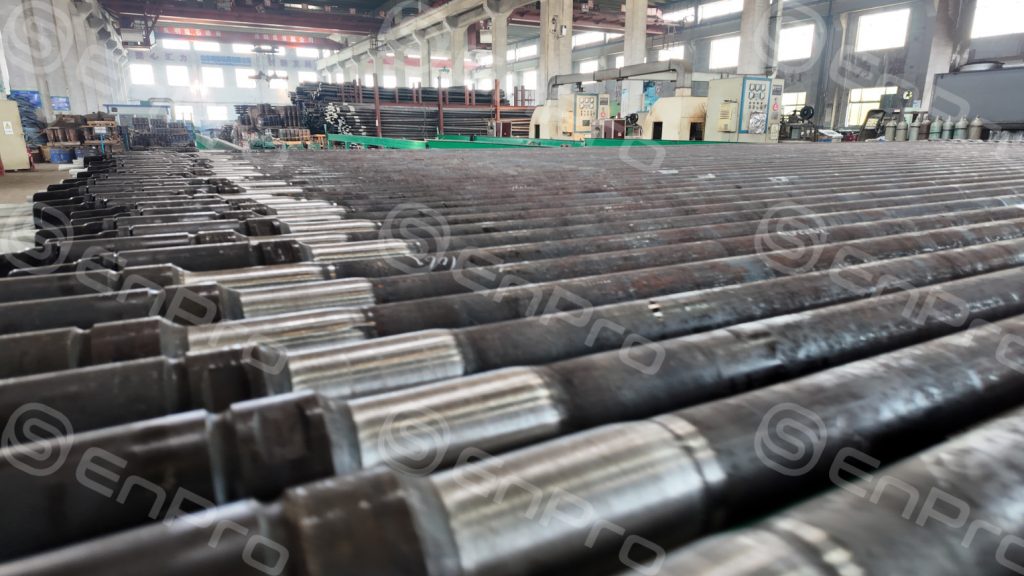
Enpro Pipe’s current drill pipe range covers 2 3/8 in. to 6 5/8 in., with wall thicknesses from 6.5 to 12.7 mm, E75/X95/G105/S135 grades, and connections from NC26 to NC50, plus 5 1/2 FH and 6 5/8 FH options.
For each configuration, we check the pipe body together with the tool-joint OD/ID, upset type and connection, because these dimensions directly affect torque capacity, mud-flow area and clearance through the wellbore or casing. When standard drill pipe and HWDP are supplied for the same string, the connection series and dimensional transition can also be coordinated before shipment, reducing compatibility problems during assembly at the rig site.
Q1: How can buyers confirm replacement drill pipe will match an existing drill string?
A1: Match the exact connection designation, tool-joint OD/ID, pipe OD and nominal weight, grade, upset type, and make-up torque basis. The same pipe OD or NC connection name alone does not define the complete drill-pipe configuration.
Q2: What drill pipe torsion-strength ratio should be checked when selecting tool joints?
A2: Standard API tool-joint OD/ID configurations are designed around a drill-pipe torsion-strength ratio of 0.80 or greater. Changing tool-joint OD or ID can reduce this ratio, so alternative configurations should be checked against the required drilling torque.
Q3: What is the API 5DP end drift requirement for drill pipe?
A3: Each drill pipe is end-drift tested through the tool joint and upset section using a cylindrical mandrel at least 100 mm (4 in.) long and with a diameter 3.2 mm (0.125 in.) smaller than the specified pin-end ID. Full-length drifting is not required by this provision.
Q4: Can API 5DP drill pipe be supplied with non-standard tool-joint dimensions or connections?
A4: Yes. ISO 11961 allows drill pipe with non-API/ISO tool joints or alternative body and tool-joint dimensions when agreed between the purchaser and manufacturer. The dimensions, tolerances, marking, and resulting performance need to be defined in the purchase specification.
Q5: What is the difference between standard HWDP and spiral heavy weight drill pipe?
A5: Standard HWDP uses a conventional heavy-wall center section, while spiral HWDP adds spiral wear pads or raised sections on the body to reduce continuous contact with the wellbore and improve clearance around the pipe. Spiral designs are often considered for directional or high-angle drilling where wall contact, drag, and wear are more significant.